/*
--------------------------------------------------
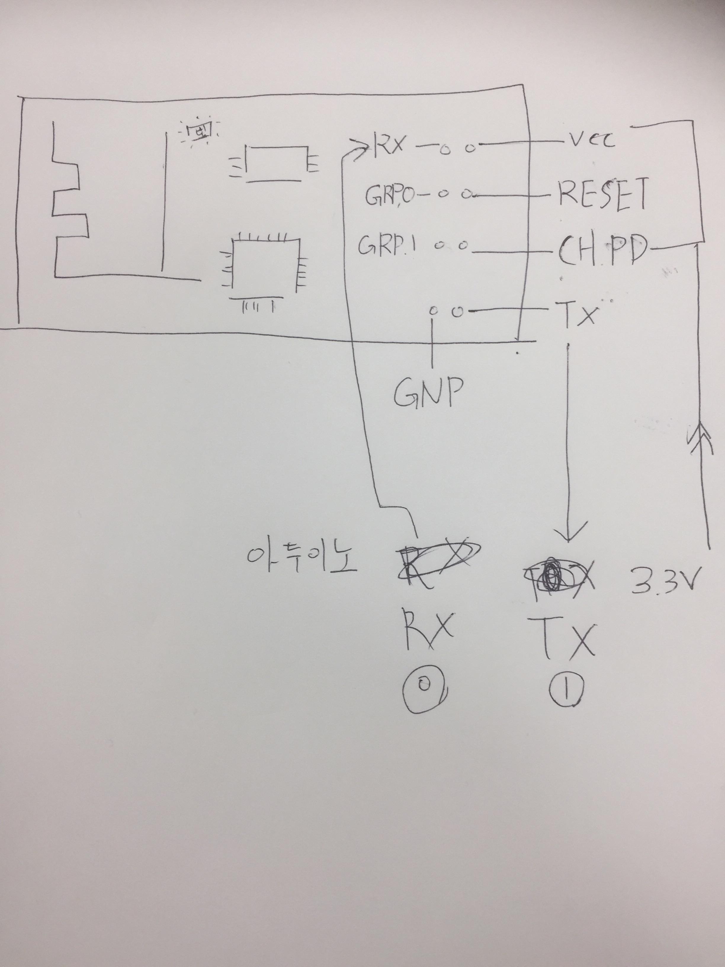
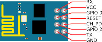
아두이노 우노 핀 ESP8266 Serial WIFI 모듈 핀
3.3V VCC, CH_PD
D0(TX) RX (레벨쉬프트 사용)
D1(RX) TX
GND GND
------------------------------------------------
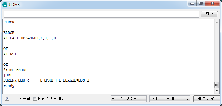
시리얼 모니터 115200bps 설정, Toth NL & CR 설정 후 아래 명령 실행
AT+RST //restart
AT+UART_DEF=9600,8,1,0,0
시리얼 모니터 9600pbs 설정 변경후
AT+RST //응답 확인
*/
void setup() {
// put your setup code here, to run once:
// Serial.begin(9600) ;
// Serial.println("AT CMD TEST 1");
}
void loop() {
// put your main code here, to run repeatedly:
}
/*
--------------------------------------------------
아두이노 우노 핀 ESP8266 Serial WIFI 모듈 핀
3.3V VCC, CH_PD
D7(TX) RX (레벨쉬프트 사용)
D6(RX) TX
GND GND
------------------------------------------------
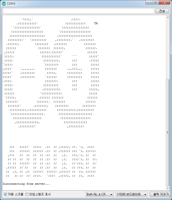
//시리얼 모니터 115200 설정, Both NL & CR 설정 후 아래 명령 실행
AT+RST ==> 응답확인 : 핀 연결 및 모듈 테스트
*/
SoftwareSerial wifi(6, 7) ; // RX, TX
void setup() {
// put your setup code here, to run once:
wifi.begin(9600) ;
Serial.begin(115200) ;
// Serial.println("AT CMD TEST 2");
}
void loop() {
// put your main code here, to run repeatedly:
if (Serial.available()) wifi.write(Serial.read()) ;
if (wifi.available()) Serial.write(wifi.read()) ;
}
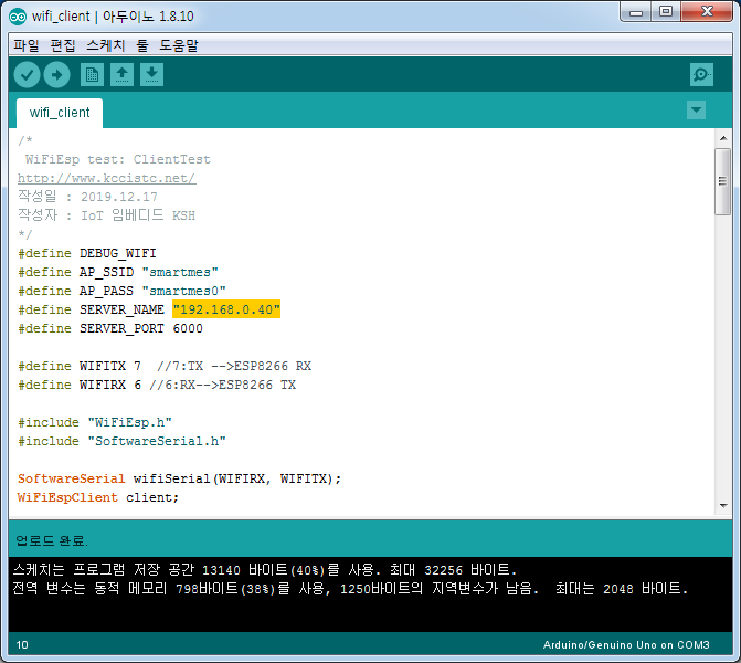
보드레이트는 115200 으로 하면 된다
그리고 디지털 0 에 있던걸 7 에 1 에 있던걸 6에 꽃아줘야한다!!!!!!!!!!!!!!!
int ledPin = 10; //LED가 연결된 아두이노의 디지털 10번(D10)은 "ledpin"으로 정의
int inPin = 7; //디지털 버튼 7
int val;

void setup() {
  // put your setup code here, to run once:
    pinMode(ledPin, OUTPUT); // ledpin(D10)은 출력
    pinMode(inPin,INPUT); // inpin(D7)은 버튼
}

void loop() {
  // put your main code here, to run repeatedly:
    val = digitalRead(inPin); //val 버튼 입력 정의
    if( val == LOW)   //val 버튼 입력이 LOW이면
      digitalWrite(ledPin, LOW);  //LED 꺼짐
    else              // 아니면
      digitalWrite(ledP in, HIGH); //LED 켜짐
}
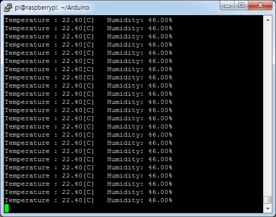
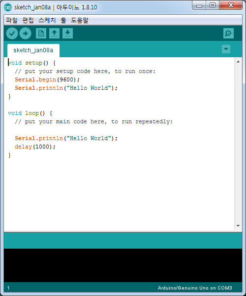
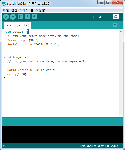
void setup() {
  // put your setup code here, to run once:
  Serial.begin(9600);
  Serial.println("Hello World");
}

void loop() {
  // put your main code here, to run repeatedly:

  Serial.println("Hello World");
  delay(1000);
}
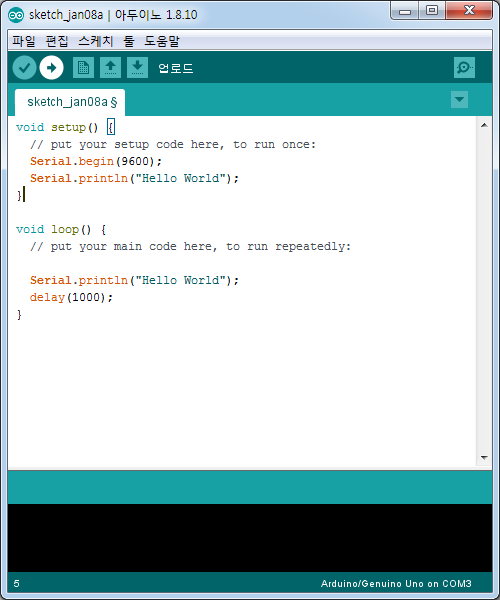
업로드
그리고
저거 누르면
실행이 된다
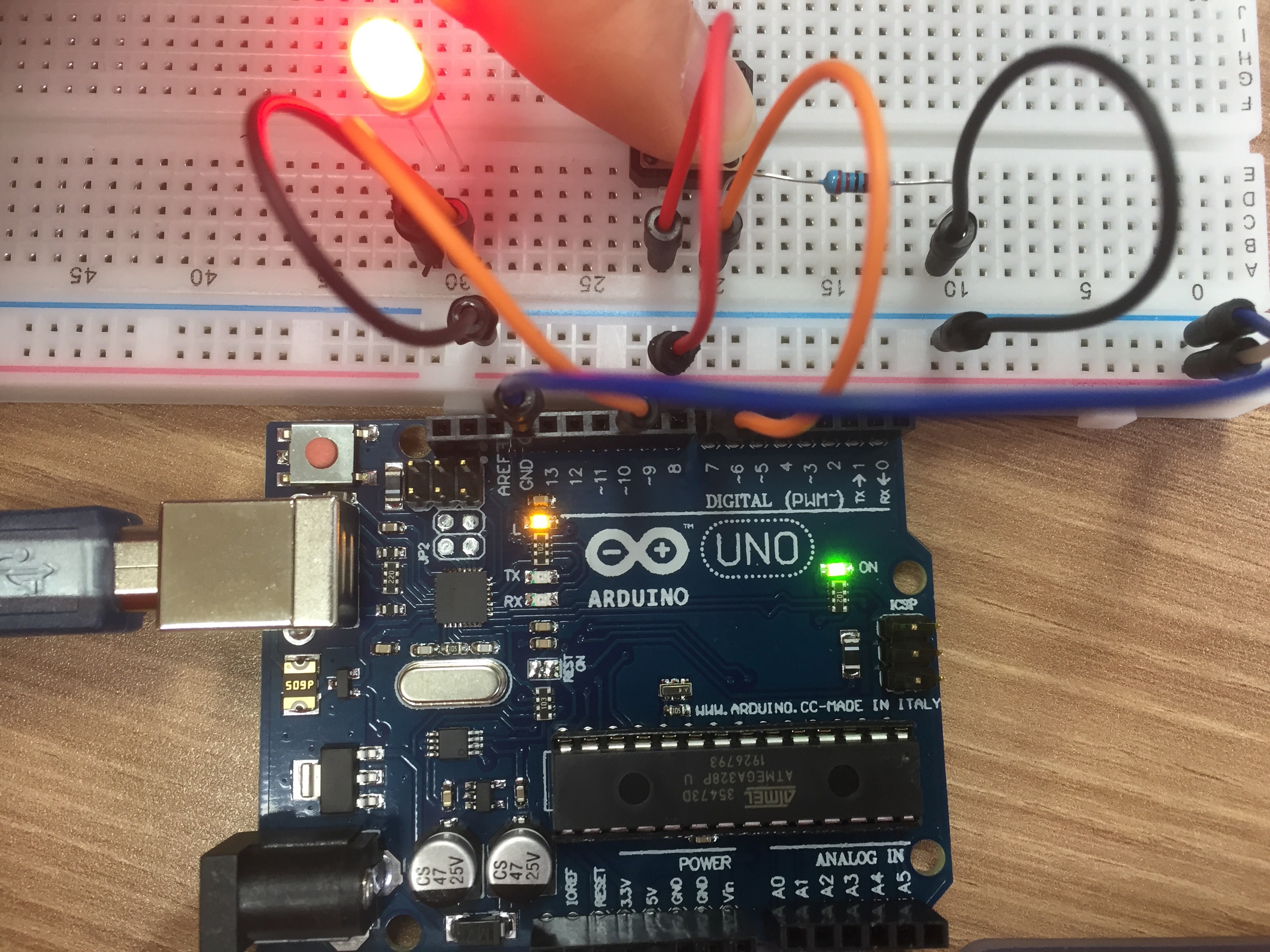
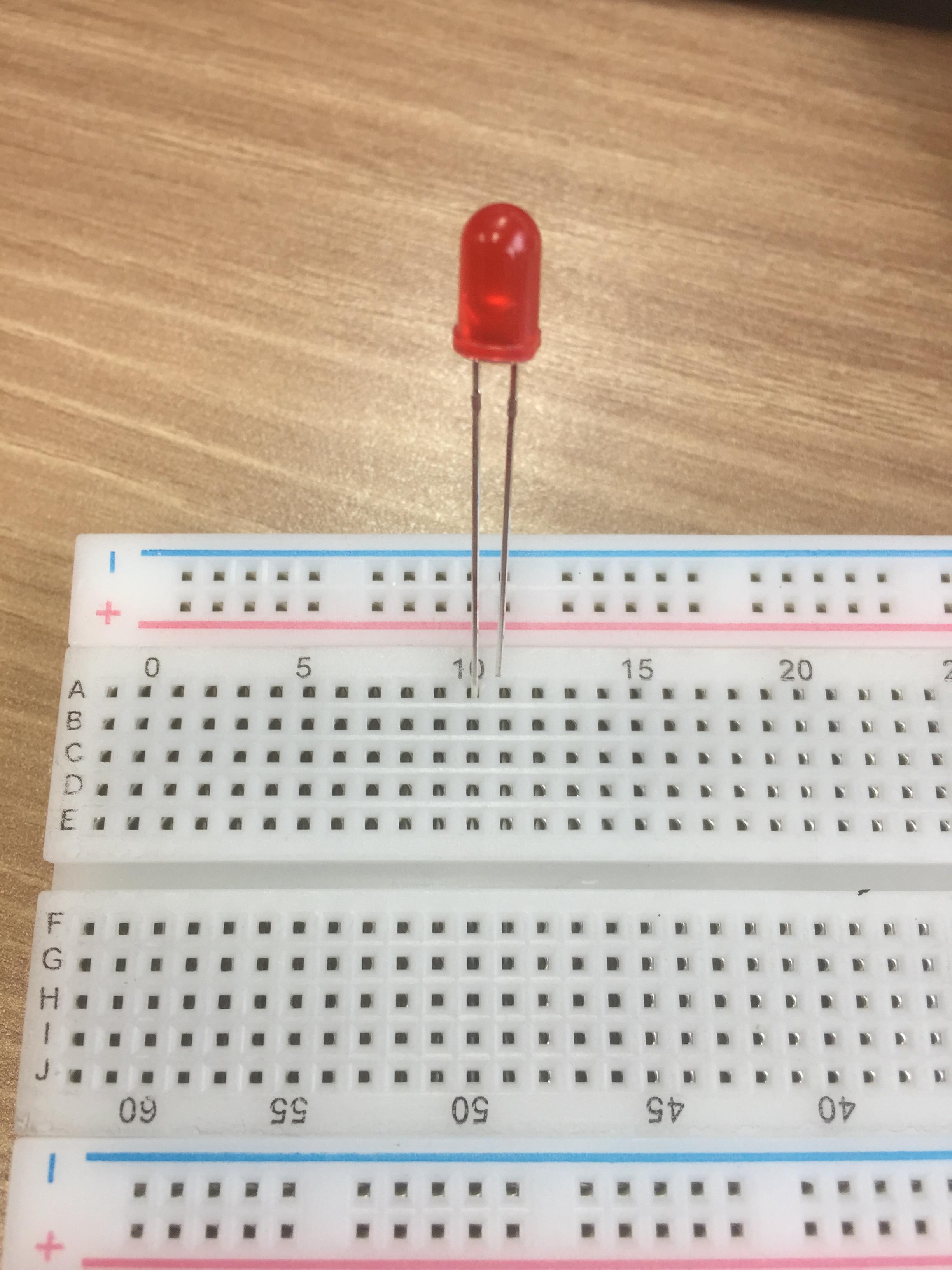
이제 LED 를 만들어보자
브레드 보드를 꺼네준다
10번이 긴거임니다!!! 긴거가 10
잘 써주고
int ledPin = 10; //LED가 연결된 아두이노의 디지털 10번(D10)은 "ledpin"으로 정의
void setup() {
  // put your setup code here, to run once:
    pinMode(ledPin, OUTPUT); // ledpin(D10)은 출력
}

void loop() {
  // put your main code here, to run repeatedly:
    digitalWrite(ledPin,HIGH); //ledpin(D10)에 HIGH의 디지털 출력
    delay(1000);

    digitalWrite(ledPin,LOW); //ledpin(D10)에 LOW의 디지털 츨력
    delay(1000);
}